(6) Check that starting motor operates only in posi tions "P" and "N".
(7) Check that reverse lights operate in position "R". (8) Adjust the transmission throttle control cable as follows:
NOTE: Before carrying out the throttle control cable adjustment ensure that the accelerator cable and engine idle speed adjustments are set to specification.
(a) Apply parking brakes fully, and position wheel chocks.
(b) Start engine and recheck idle speed when normal operating temperature is reached.
(c) Stop engine (for safety reasons). Adjust outer cable so that the cable crimped sleeve (on original cable only) just contacts the abutment.
(d) Connect tachometer to read engine r.p.m.
(e) Install a hydraulic gauge, Tool No. E21C65A to read line pressure. The gauge tapping point is located at the rear of the transmission housing above the oil pan mounting flange.
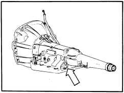
Fig. 29-Line pressure tapping
(f) Start the engine and select "D" drive range (brakes fully applied).
(g) Note the engine r.p.m. and the line pressure with the transmission at operating temperature. The line pres sure should be 420 to 520 kPa (60 to 75 p.s.i.).
(h) Use the accelerator pedal to increase the engine speed 500 r.p.m. and note the increase in transmission pressure. The increase in pressure must be a minimum of 70 kPa (10 p.s.i.). It may be necessary to lightly shake the transmission throttle cable outer casing during the operation to overcome cable drag.
(i) To increase the pressure rise, turn the cable adjust ing nuts to widen the gap between the end of the outer cable casing and the crimp sleeve on the inner cable. To decrease the pressure rise, close the gap between the end of the outer cable casing and the crimp sleeve. Remove the cable crimp sleeve if correct adjustment cannot be achieved. After setting, fit a new crimp sleeve, Part No. 3649292.
. .,
1-2-17
NOTE: Duration of test must be limited to a few seconds to prevent transmission overheating. Select "N" Neutral and return engine to idle speed whilst making necessary cable adjust ments.
SUSPENSION, STEERING AND BRAKES Steering and Suspension Ball Joints
Inspect condition of all ball joint seals. Seals that are cut, torn, damaged or loose fitting must be replaced.
Check ball joints for excessive wear.
NOTE: Early lower suspension ball joints have a buUt in free play from new. This free play must not exceed 1,78 mm (0.070") and should be checked in accordance with the procedures out lined in Group 2 - Front Suspension. Later ball joints, stamped Dofor on lower face, should not exhibit any axial free travel.
Front Wheel Bearing Adjustment (1) Raise wheel clear of floor.
(2) Remove dust cap, split pin and nut lock.
(3) Inspect for presence and condition of lubricant (clean and repack if necessary).
(4) Tighten wheel bearing adjustment to specified torque using a torque wrench whilst rotating the wheel. (5) Position nut lock on adjusting nut so that one pair of split pin slots align with pin hole in spindle.
(6) Back off adjusting nut and lock assembly one slot and install a new split pin, locking it securely.
(7) Clean grease cap, coat inside with wheel bearing lubricant (do not fill) and install cap.
(8) Lower wheel to floor.
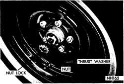
Fig. 3D-Front wheel bearing installation
Front Wheel Bearing Lubrication
(1) Loosen front wheel retaining nuts, raise the front of the vehicle and place on safety jacks.
(2) Mark the position of front wheels to hub and re move both wheels.
(3) Remove the two mounting bolts and lock plates securing the brake caliper to stub axle; then lift the cali per assembly away from the disc.
REV. OCT. '78
.. )