Orifice Spark Advance Control (OSAC) Valve
Proper operation of this valve depends on air-tight fittings and hoses and on freedom from sticking or plug ging due to deposits.
Hose connections between valve, carburettor and dis tributor shall be inspected. Any hardened or faulty hoses that may allow air leakage must be replaced. Operation of the valve shall be checked using the following proce dure:-
With engine running at 2000 r.p.m, in neutral, dis connect hose at OSAC valve that leads-to the distributor. Attach vacuum gauge to this vacuum fitting. The valve is operating properly if a very gradual increase in vacuum is observed, it will take approximately 20 seconds to reach a stabilized level (this will vary with different engines and vehicles). If vacuum increases immediately (to the same level as manifold vacuum) the OSAC valve is not operating properly and must be replaced. If no in crease in vacuum is observed, the valve is not operating properly and must be replaced. Ambient temperature in the area of vehicle must be above 20°C (68 "F) for this test when the vehicle is equipped with a Thermal Ignition Control Valve.
TO DISTRIBUTOR
V ACUUM ADVANCE HOSE~
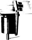
TO CARBURETOR VACUUM PORT
PF191A
Fig. 18-0SAC valve
Exhaust Gas Recirculation (EGR) System
To assure proper functioning of this system, all pas sages and moving parts must be free from plugging or sticking as a result of deposits. It is also important for the entire system to be free from leaks. Any hoses or components found to be leaking must be replaced.
Inspect all hose connections between carburettor, in take manifold and EGR control valve. Replace any hoses that are hardened or cracked and any faulty connectors.
Remove the EGR valve and inspect for deposits and damage. Clean deposits or replace the valve as necessary. Use a new flange gasket between the valve and manifold after any EGR valve removal.
Operation of the EGR control valve shall be checked with the engine warmed up and running. Allow the engine to idle in neutral with the carburettor throttle closed;
1-2-11
then quickly accelerate engine speed to approximately 2000 r.p.m. Movement of the valve stem during the period of acceleration should be visible by observing a change in relative location of the groove on the stem.
NOTE: On vehicles fitted with a vacuum delay valve the operation of the EGR valve will be delayed by 2 to 5 seconds.
If defective operation is indicated, the problem shall be diagnosed using the test procedure described in Group 25 - Emission Control System.
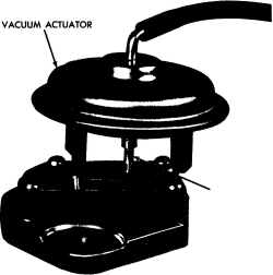
VALVE STEM
PFl93
Fig. 19-EGR control valve
After verifying that the control stem is functioning correctly, a check should be made to assure that exhaust gas is actually flowing through the valve and passages. Remove the hose connected to the valve and apply a vacuum signal of at least 33 kPa (10" Hg) directly to the valve with the engine warm and idling in neutral. The intake manifold vacuum is usually about 33 kPa (10" Hg) at idle and would be convenient to use for this purpose. Idle speed should drop 150 r.p.m. or more (some engines may stall) when this vacuum signal is applied to the valve. This speed change confirms that exhaust gas recirculation is taking place.
Reverse Flush Cooling System
The use of a flushing tool is recommended for this
| operation. | . |
(1) Remove drain plugs or open drain taps in the radiator and cylinder block.
(2) Disconnect the hoses from the radiator, engine and the water pump, then remove the thermostat and re-install the housing. Move heater heat control to the ON position. (3) Connect the flushing gun as described in the manu facturer's instructions and proceed to flush both the cylinder block, radiator and heater.
(4) Ensure that the water is clear at the drain outlets at the conclusion of the flushing procedures. Then re-
REV. AUG. '77