(11) Install new limit caps with stops 45° from rich limit.
(12) Adjust throttle kicker (8 cyl. man. trans. with E.L.B.) as follows: Disconnect vacuum line from kicker and loosen locknut. Screw throttle kicker in or out until a clearance of 0,13 mm (0.005") is obtained between the end of the kicker pushrod and the throttle lever when the throttle lever is held against the curb idle screw stop by the throttle return spring. Tighten the lock nut.
| Engine | Eng. r.p.m, X | Eng. r.p.m. Y |
| 6 Cylinder | 900 | 750 |
| 8 Cyl. (auto.) | 850 | 750 |
| 8 Cyl. (man.) | 850 | 800 |
| 8 Cyl. (auto.)" | 900 | 800 |
| 8 Cyl. (man.)" | 900 | 850 |
| • Models equipped with E.L.B. system. | ||
Carburettor Fast Idle Cam and Pivot Pin
It is necessary for the fast idle cam and pivot to oper ate freely. To ensure free operation, apply penetrating oil to the fast idle cam and pivot to remove dirt, oil or other deposits that could cause sticking or erratic motion.
Carburettor Choke Shaft
It is necessary for the choke shaft to operate freely.
The carburettor choke shaft should be serviced with pene trating oil to prevent sticking from gum deposits.
Automatic Choke System
With the engine turned off, partially open the throttle and check entire choke system for freedom of operation throughout its full travel. Any stiffness or binding of the linkage must be corrected.
On Vehicle CarbureUor Adjustments CARTER BBD:
Choke Vacuum Kick Adjustment
The choke diaphragm adjustment controls the fuel delivery while the engine is running. It positions the choke valve within the air horn by action of the linkage between the choke shaft and the diaphragm.
The diaphragm must be energized to measure the vacuum kick adjustment. Vacuum is supplied by the vehicle on which the carburettor is fitted.
(1) As the adjustment is to be made with engine run ning, disconnect fast idle linkage to allow choke to close to the kick position with engine at curb idle.
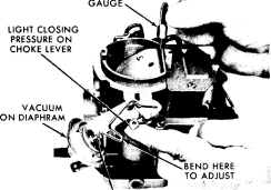
(2) Insert specified gauge (refer to Specifications) be tween choke valve and wall of air horn (Fig. 10). Apply sufficient closing pressure on lever to which choke rod attaches to provide a minimum choke valve opening without distortion of diaphragm link. Note that the cylin-
1 - 2 - 7
i
I
drical stem of diaphragm will extend as internal spring is compressed. This spring must be fully compressed for proper measurement of vacuum kick adjustment.
(3) Adjustment is necessary if slight drag is not obtained when removing the gauge. Shorten or lengthen diaphragm link to obtain correct choke valve opening. Length changes should be made carefully opening or closing the If-bend provided in the link. Improper bend ing causes contact between the V-section and the diaphragm assembly.
CAUTION: Do not apply twisting or bending force to diaphragm.
}
TO VACUUM SOURCE
STEM FULLY DEPRESSED
PK191
Fig. lo-Adjusting choke vacuum kick
(4) Reinstall vacuum hose on correct carburettor fitting. Return fast idle linkage to its original condition as it was before step No.1.
(5) Make the following check. With no vacuum applied to diaphragm, the Choke Valve should move freely be tween open and closed positions. If movement is not free, examine linkage for misalignment or interferences caused by bending operation. Repeat adjustment if necessary to provide proper link operation.
Choke Unloader (Wide Open Kick)
The choke unloader is a mechanical device to par tially open the choke valve at wide open tllrottle. It is used to eliminate choke enrichment during cranking of an engine. Engines which have been flooded or stalled by excessive choke enrichment can be cleared by use of the unloader. Adjust the choke unloader as follows:
(1) Hold throttle valves in wide open position. Insert specified gauge (see Specifications) between upper edge of choke valve and inner wall of air horn.
(2) With a finger lightly pressing against choke lever, a slight drag should be felt as gauge is being withdrawn. If an adjustment is necessary, bend unloader tang on throttle lever until correct opening has been obtained. (Fig. 11).
REV. OCT. '78