Installation
(1) Install new strut bushings, if necessary.
(2) Position the strut into the lower control arm and tighten the retaining nut to specification.
(3) Install the lower control arm, shaft and strut assembly.
LOWER BALL JOINTS
The lower balljoint is integral with the steering arm and is not serviced separately.
Inspection
(1) Raise the front of vehicle and install safety floor stands under both lower control arms as far outboard as possible. The upper control arms must not contact the rubber rebound bumpers.
(2) With the weight of vehicle on the control arm, in stall dial indicator and clamp assembly to lower control arm (Refer Fig. 12).
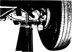
NU194
Fig. 12-Measuring lower balljoint axial travel
(3) Position dial indicator plunger tip against balljoint housing assembly and zero dial indicator.
(4) Measure axial travel of the balljoint housing arm with respect to the balljoint stud, by raising and lowering the wheel using a pry bar under the centre of the tyre,
NOTE: Maximum axial travel of the baDjoint stud, relative to the housing (early balljoints) should not exceed 1,77 mm (0.070"). Replace balljoints exceeding this limit. Later balljoints, stamped Dufor on lower face, should not exhibit any axial free travel.
Removal
(1) Remove the upper control arm shoulder bumper. (2) Raise the vehicle so the front suspension is in full rebound (under no load) and slacken the torsion bar ad juster. If jacks are used to raise the vehicle it is essential that a support be used between the "K" member and jack.
(3) Remove wheel assembly.
2-2-8
(4) Remove the two screws attaching the steering arm and balljoint assembly to the steering knuckle.
(5) Remove the tie rod end from the steering arm using Tool E2C15. Use care not to damage seal.
(6) Using Tool E2C5A remove the balljoint stud from the lower control arm (Refer Fig. 9) and remove the steering arm and balljoint assembly.
Installation
(1) Place a new seal over the balljoint making certain the lip of the seal is seated on the balljoint housing using Tool E2C20A (Refer Fig. 13).
(2) Position the steering arm and balljoint assembly on the steering knuckle and install the two screws and tab lock washers and tighten to specified torque.
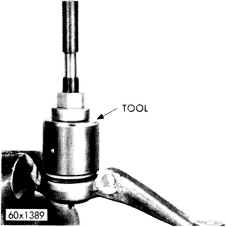
Fig. 13-InstalliIlg lower balljoint seal using Tool E2C20A

~ .........•. \
62x58
Fig. 14-Removing upper balljoint stud (Tool E2CI5D)
REV. OCT. '78