(7) Cut and remove the rubber portion of the bushing from the control arm shaft.
(8) Insert ali" N.F. 12 T.P.1. tap into the pivot 'shaft bushing outer shell, approximately one half the depth of the bushing.
(9) Using a hand press and a blunt drift, force the bushing out of the control arm (Refer Fig. 10).
(10) Remove the bushing shell from the tap.
(11) Remove the bushing inner shell from the pivot shaft, cutting off if necessary.
Assembly
(1) Position the new bushing on the shaft (flange end of bushing first) and seat bushing on the shoulder of the shaft.
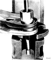
Fig. 100Removing bushing shell from control ann
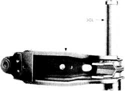
(2) Press the shaft and bushing assembly into the lower control arm using Tool E2C2SC and an arbor press (Refer Fig. 11).
(3) Install the torsion bar adjusting bolt and swivel. (4) Install the jounce bumper on the control ann and tighten to specified torque.
(5) Position the strut in the lower control ann and tighten nut to specified torque.
Installation
(1) Position the lower control arm shaft and strut into their respective mountings in the "K" member. The strut bushing retainer, bushing half and sleeve should be placed over the shaft before the strut is inserted into the "K" member.
(2) Install the bushing half and outer retainer. Install retainer nut finger tight only.
(3) Install the lower control arm shaft washer and nut finger tight only.
2-2-7
lO\VER CONTROL ,.\F:Nt
6Ox1390
Fig. II-Installing shaft assembly in lower control arm
(4) Position the lower ball joint stud into the lower control arm and tighten the nut to specified torque. Install the split pin.
(5) Position the steering knuckle arm on the steering knuckle and install the two screws and lockwashers.
(6) Tighten screws to specified torque then bend the lock tabs (away from the rubbers) to secure the screws.
(7) Inspect tie rod seals for damage and replace if damaged. Connect the tie rod end to the steering knuckle arm and tighten the nut to specified torque. Install the split pin.
NOTE: Shock absorber bolt nut must face forward.
(8) Connect the shock absorber to the lower control
arm and tighten the nut.
(9) Install the torsion bar.
(10) Install the wheel assembly.
(11) Lower the vehicle to the floor and re-install the anti-sway bar link to the lower arm brackets (if applic able).
(12) Tighten strut nut at "K" member (install pin if applicable) and lower shock absorber bolt to specified torques.
(13) Adjust the front suspension height.
(14) Tighten the lower control arm shaft nut to speci fied torque and install the split pin.
(15) Check and adjust the front suuspension align ment.
LOWER CONTROL ARM STRUT Removal
(1) Remove the lower control arm, shaft and strut as an assembly.
(2) Remove the nut holding the strut to the lower control arm.
(3) Remove the strut from the lower control arm. In spect bushings for wear or damage.
,