The pickup coil signal is a reference signal. When it is received by the computer, the maximum amount of timing advance is made available. Now based on the data from all the sensors the computer determines how much of this maximum advance is needed at that instant.
Finally, if for some reason, there is a failure of the computer, the system will go into what is called the limp in mode. This will enable the driver to continue to drive the vehicle until it can be repaired. However, while in this mode, very poor performance and fuel economy will be given by the system. If there is a failure of the pickup coil or start mode of the computer, the engine will not start or run.
IGNITION SYSTEM STARTING TEST
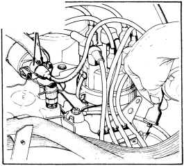
Remove coil wire from distributor cap. Hold end of wire about 6 mm (l/4") away from a good engine ground (Fig. 5). Have a helper crank the engine while you' look for a spark at coil wire.


Fig. 5- Testing for spark during cranking
If there is a spark at coil wire it must be constant and bright blue in colour. If it is, have helper continue to crank engine and while slowly moving coil wire away from ground, look for arcing at the coil tower (Fig. 6). If arcing occurs replace coil. If spark is weak or not constant or there is no spark, proceed to the "Failure To Start Test."
If spark is good or there is no arcing at the coil tower the ignition system is producing the necessary high sec ondary voltage. However make sure that this voltage is getting to the spark plugs by checking the distributor rotor, cap, spark plug wires, and spark plugs. If they are okay then the ignition system is not the reason why the engine will not start. It will be necessary to check the fuel system and engine mechanical items.
8 - 5M- 4
~~
~ CHECK HERE <; FOR ARCING
Fig. 6- Testing for arcing .at coil tower
FAILURE TO START TEST
NOTE: Before proceeding with this test make sure "Ignition System Starting Test" has been performed. FaUure to do this may lead to unnecessary diagnostic time and wrong test results.
(1) With a voltmeter measure and note voltage at battery. Battery specific gravity must be at least 1.220 temperature corrected in order that it can deliver the necessary voltage to operate the cranking and ignition systems properly.
(2) Disconnect wiring harness connector from "Coolant Switch."
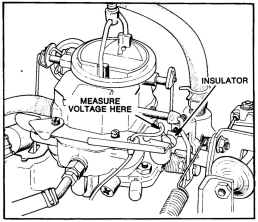
Fig. 7-Power check
ISSUED OCT. '78