8 - 5M - 3
Pick Up Coil
Located in the distributor, it supplies the basic timing signal to the computer. Except during cranking this signal will tell the computer to create the maximum amount of timing advance available for any engine r.p.m. The com puter can also determine from this signal, engine speed and when each piston is coming up on its compression stroke.
Coolant Temperature Sensor (Fig. 3)
Located so that it can sense engine coolant temperature, its signal tells the computer when engine coolant tempera ture is below 65°C (150°F).
Throttle Position Transducer (Fig. 4)
Located on the carburettor, its signal tells the computer the position and the rate of change of the throttle plates.
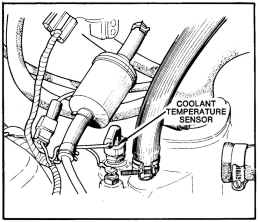
Fig. 3-Coolant temperature sensor (eight cyl. model)
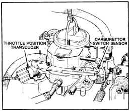
Fig. 4--Carburettor sensors
ISSUED OCT. '78
Additional spark advance will be given by the computer when the throttle plates start to open, and in every position to full throttle.
Carburettor Switch Sensor (Fig. 4)
Located on the side of carburettor, its signal tells the computer if the engine is at idle or off idle.
Vacuum Transducer (Fig. 2)
Located on the computer, its signal tells the computer what engine manifold vacuum is. The higher the vacuum, the more additional advance will be given. The lower, the less amount of advance. In order to obtain the maximum amount of advance for any 25 mm (inch) of vacuum, the "Carburettor Switch Sensor" must remain open for a specified amount of time. During that time the advance will not happen quickly but will build up at a slow rate. If the carb switch closes before the predetermined time period, the build up of advance at that time will be can celled in the ignition system, however, the computer will put it into memory and slowly return h: to O. If the switch is reopened before the advance is returned to 0, the build up of advance starts at the point where the computer still has it in memory. If the switch is reopened after the advance is returned to 0, the build up of advance must start all over again.
System Operation
There are two functional modes of the spark control computer. They are start and run. The start mode will only function during engine cranking and starting. The run mode will only function after the engine starts and during engine operation. The two will never operate together.
For cranking and starting the pickup coil in the distribu tor feeds its signal to the computer. During this time the start mode is functioning and the run mode is bypassed. A fixed quantity of advance will be established in the ignition system because of the permanent position of the pickup coil. The amount of advance in this mode will be determined by the position of the distributor.
After the engine starts and, during engine operation the pickup coil signal continues to feed into the computer. Now the run mode is functioning and the start mode-is bypassed. The amount of advance will now be determined by the computer based on information received from all the sensors. Another point to remember is that the start mode will take over in the event of a run mode failure. The engine will keep running but since the start mode timing remains fixed, performance will be below standard.
Also after starting the computer will create additional advance and will maintain it for approximately one minute. However, during that time period that additional advance will slowly be eliminated. With the engine run ning and if the engine coolant temperature is below 65°C (l50°F) the "Coolant Temperature Sensor" will signal the computer of this preventing any additional spark advance from the "Vacuum Transducer" signal. After the engine reaches operating temperature, normal system operation will begin.