8 - 5M - 9
Vacuum Advance Schedule Test
(1) Connect and adjust timing light to engine so total timing advance at crankshaft can be checked.
Start engine and if it is not at operating temperature wait a few minutes until it is. Make sure transmission is in neutral and parking brake is on.
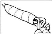
(2) Disconnect Throttle Position Transducer. Place a thin insulator (piece of paper) (Fig. 22) between carb switch and curb idle adjustment screw or position throttle linkage on fast idle cam. If curb idle adjustment screw is not touching carb switch make sure fast idle cam is not on or is binding, linkage is not binding, or throttle stop screw is not over adjusted. Adjust timing light so basic timing signal is seen at the timing plate. The meter on the timing light should show additional amount of 'advance off idle' as indicated under specifications. If advance is not within specifications replace "Spark Control Computer." If it is let engine run at least 9 minutes and make sure there is a minimum of 380 mm (15") of vacuum at trans ducer.
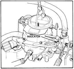
Fig. 22-Preparing for vacuum advance schedule test
(3) After 9 minutes adjust timing light so basic timing signal is seen at the timing plate. The meter on the timing light should show additional amount of 'vacuum advance' as indicated under specifications. If advance is not within specifications replace "Spark Control Computer." If it is proceed to Step 4.
(4) Remove insulator that was installed at carb switch or take throttle linkage off fast idle position and timing should return to basic setting. If timing does not return, make sure curb idle adjustment screw is touching carb switch. Then turn engine off and check the wire between terminal 7 (Fig. 23) of connector at bottom of computer and carb switch terminal for opens, shorts or poor con nections. If check out is okay repeat test and if timing still will not return, replace "Spark Control Computer."
@@ @@
| CHECK WIRE | ~ ~ |
| BETWEEN | ~ ~ |
TERMINAL 7
CARB~~~TTOR --ti-@ @
T~~~~~~L e e
Fig. 23-Connector test (vacuum transducer test)
ADJUSTING THROTTLE POSITION TRANSDUCER
(1) Start engine and wait 90 seconds for the start timer advance schedule to run out (engine must be at normal operating temp.)
(2) Ground out carb switch with jumper wire, pull off throttle transducer connector to prevent any signal from reaching the computer.
(3) Check idle speed and timing at crankshaft, adjust to specifications if necessary.
(4) Reconnect electrical connector to transducer and recheck timing at crankshaft.
(5) Recheck timing and if timing is greater than specified, loosen transducer locknut and turn transducer clockwise until timing returns to specified limits. Then turn an additional half turn clockwise and tighten locknut.
REPAIR PROCEDURES
Service procedures are the same as described under
. Ignition System for the following items:
(a) distributor, cap and rotor
(b) coil
(c) ballast resistor
(d) spark plug wires and spark plugs (e) pick up coil.
Spark Control Computer
When it becomes necessary to replace the computer, remove mounting screws from inside of air cleaner. DO NOT TAKE APART COMPUTER FOR ANY REA SON. IT IS NOT SERVICEABLE AND IS TO BE REPLACED AS AN ASSEMBLY.
ISSUED OCT. '78