CHECK RESISTANCE /=::::; BETWEEN TERMINALS
u
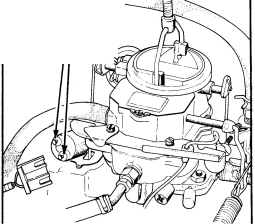
Fig. 18--Check for resistance at throttle transducer terminals
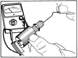
Fig. 19- Throttle position transducer - power check
(4) Position throttle linkage on fast idle cam, ground the carb switch with a jumper wire, disconnect wiring harness connector from "Throttle Position Transducer," and connect it to a known good transducer of the same type that can be used for testing.
(5) Move core of' test transducer in so that it is fully bottomed out (Fig. nO), start engine, wait 90 seconds and then move core out about 25 rom (I") (Fig. 21).
(6) Adjust timing light so the basic timing signal is seen at the timing plate. The meter on the timing light should show additional amount of 'throttle advance' as indicated under specifications. If it is within specifications, move core back into transducer and timing should return to basic setting. If timing did not advance and/or did not return, replace "Spark Control Computer." Also after
8 - 5M - 8
replacing computer recheck "Throttle Position Trans ducer" as described in Step 3 to make sure it is now okay. If not, replace.
(8) Remove test transducer and reconnect all wiring.

CORE FULLY BOnOMED OUT
Fig. 2O--Checking with test transducer - core bottomed out

Fig. 21--Checking with test transducer - core extended
TESTING FOR POOR FUEL ECONOMY AND UNUSUALLY HIGH IDLE SPEED
Coorant Switch Test
(1) Connect one lead of ohmmeter to a good ground on engine.
(2) Connect other lead of ohmmeter to terminal of coolant switch and check for continuity. The ohmmeter readings should be as follows:
For Engine Cold
(1) Continuity should be present at terminal. If not, replace coolant switch.
For Engine Above &SoC (150°F) Or At Operating Temperature (Thermostat Open)
Terminal reading should show no continuity, if it does, replace coolant switch.
ISSUED OCT. '78