(12) After installing new computer and engine still fails to start, reinstall original one and repeat test procedure because more than likely one of the test procedures was not done correctly.
TESTING FOR POOR PERFORMANCE Start Timer Advance Schedule Test
(1) Connect an adjustable timing light (Fig. 16) to engine so that total timing advance at crankshaft can be checked.
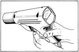
Fig 16-Adjustable timing light
(2) Have a helper start engine, in neutral, snap throttle open and closed.
Look at timing mark on crankshaft damper immediately after the engine has started and adjust timing light so the basic timing signal is seen at the timing plate. The meter on the timing light should show amount of 'start-up advance' as indicated under specifications.
NOTE: Reading could start to change after the engine has run for 10 sees.
Continue to observe timing for 90 seconds while adjust ing timing light to maintain basic timing signal. The addi tional advance should slowly reduce to the basic timing signal after approximately 90 sees. If timing did not increase and/or did not return to basic, replace "Spark Control Computer." If it checked out okay proceed to "Throttle Advance Schedule Test."
NOTE: Do not remove timing light because it is to be used for further testing.
SPEED ADVANCE SCHEDULE
Before proceeding with this test, make sure that the basic timing and hot curb idle are within specifications. Connect a jumper wire between the carburettor switch terminal and a good ground. Disconnect the wiring harness connector from the throttle position transducer.
Start and run the engine for two minutes. Raise the r.p.m. to specified test level and adjust timing light so that basic timing is seen at the timing indicator. The 'addi tional speed advance' seen on the timing light meter should be as specified. If not, replace computer and repeat this test. If it is as specified, proceed to the next test.
ISSUED OCT. '78
8 - 5M - 7
ThroUie Advance Schedule Test
NOTE: Before proceeding with test make sure "Throttle Position Transducer" is adjusted properly. Refer to adjustment procedure.
(1) Make sure ignition switch is in the "OFF" position and then disconnect connector from bottom of "Spark Control Computer."
(2) With an ohmmeter measure resistance between terminals 8 and 9 of connector (Fig. 17). Resistance should be between 60 and 90 ohms. If it is, reconnect connector and proceed to Step 3. If it isn't, remove con nector from "Throttle Position Transducer" and measure resistance at transducer terminals (Fig. 18). If resistance is now between 60 and 90 ohms, this means there is an open, short, or poor connection of the wires between terminals 8 and 9 of connector and terminals that connect to the transducer. If resistance is not within specifications replace "Throttle Position Transducer" and proceed to Step 3.

| CHECK | (@ @ |
RESISTANCE __ I ~ 10\ AT TERMINAL "t1~ ~
| 8-9 | 1m @ |
@@ (9)@
Fig. 17-Connector test (throttle transducer)
(3) Reconnect all wiring and turn ignition switch to the "Run" position but do not start engine. Connect negative lead of a voltmeter to a good engine ground. With positive lead of voltmeter, touch one terminal of "Throttle Position Transducer," (Fig. 19). While opening throttle of carburettor all the way and then closing, watch voltmeter reading. Do the same with other terminal of transducer. Either one of the terminals should show approximately a 3 to 6 volts change on the voltmeter when throttle is opened and closed. If 3 to 6 volts is there pro ceed to Step 4. If there isn't do not replace transducer yet because "Spark Control Computer" can cause transducer not to work properly. It will be necessary to proceed to Step 4 to check this.