8 - 5M - 5
(3) Place a thin insulator (piece of paper) (Fig. 7) between curb idle adjusting screw and carb switch or make sure curb idle adjusting screw is not touching carb switch, by placing on 'fast idle' portion of cam.
(4) Connect negative lead of a voltmeter to a good engine ground.
(5) Tum ignition switch to "Run" position and measure voltage at carb switch terminal (Fig. 7). If voltage is greater than 5 volts but less than 10 volts proceed to Step 7. If voltage is greater than 10 volts check to insure con tinuity between terminal 10 of dual connector and ground (Fig. 8).
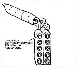
Fig. 8-Connector test (power check)
If voltage is not at least 5 volts tum ignition switch to the "OFF" position and disconnect connector from bottom
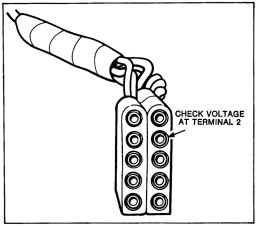
Fig. 9-Connector test (power check)
of "Spark Control Computer." Tum ignition switch back to the "Run" position and measure the voltage at terminal 2 (Fig. 9) of connector. Voltage should be within I volt of previously noted battery voltage. If voltage is correct, proceed to Step 6. If it isn't check the wiring between terminal 2 of connector and ignition switch for opens, shorts or poor connections.
(6) Tum ignition switch to the "OFF" position and disconnect connector from bottom of "Spark Control Computer." Check with an ohmmeter for continuity between terminal 7 of connector (Fig. 10) and carb switch terminal. There should be continuity between these two points. If not, check wire between them for opens, shorts or poor connections. If there is, check for continuity between terminal 10 of connector and ground. If there is continuity, replace "Spark Control Computer." If there isn't, check wire for opens or poor connections and only proceed to Step 7 if engine still fails to start.
@@
@@
| CHECK FOR | @ @ |
CONTINUITY BETWEEN
TERMINAL 7 AND ~ 'CJh CARBURETTOR SWITC~ ~
TERMINAL (§) @
Fig. IO-Connector test (power check)
CHECK FOR VOLTAGE BETWEEN ~ ~ TERMINAL 1
\QI g I GR~J'ND
@@ @@ @(Q)
@@
ISSUED OCT. '78
Fig. ll-Connector test (primary circuit)