(7) Turn ignition switch to the "Run" position and with positive lead of voltmeter measure voltage from terminal 1 of disconnected lead from computer and ground (Fig. 11). Voltage at each should be within 1 volt of previously noted battery voltage. If it is, proceed to Step 8. If not, check wiring and connections between terminal connector and ignition switch.
(8) Turn ignition switch to the "OFF" position and with an ohmmeter measure resistance between terminals 5 and 9 of dual connector (Fig. 12). Resistance should be between 150 and 900 ohms. If resistance is 150 to 900 ohms proceed to Step 9. If it is not, disconnect "Pick Up" coil leads from distributor. Measure resistance at lead going into distributor (Fig. 13). If resistance is now between 150 and 900 ohms, this means there is an open,
CHECK FOR RESISTANCE
BETWEEN --
TERMINALS 5 AND 9
Fig. 12-Connector test (pick-up coil)
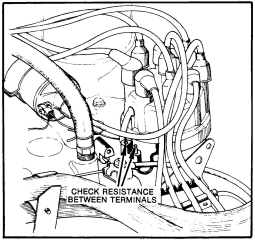
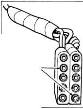
Fig. 13-Checking pick-up at distributor leads
8 - 5M - 6
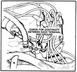
Fig. 14-Checking pick-up for ground
shorted, or poor, connection between distributor connector and terminals 5 and 9 of dual connector. If resistance is still out of specifications, the "Pick Up" coil is bad.
(9) Connect one lead of ohmmeter to engine ground and with other lead check for continuity at each terminal of lead going into distributor (Fig. 14). There should be no continuity. Reconnect distributor lead and proceed to Step 10. If there is continuity, replace "Pick Up" coil.
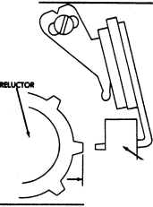
(10) Remove distributor cap and check air gap of "Pick Up" coil (Fig. 15). If it is not within specifications, adjust. If it is, proceed to next step.
(11) Install distributor cap, reconnect all wiring and try to start engine. If engine still fails to start, replace "Spark Control Computer."
| I I | PICK-UP |
~AIRGAP
Fig. 15-Checking pick-up air gap
ISSUED. OCT. '78