(8) Fully depress the secondary piston and install the reservoir attaching bolt and new gasket. Hand screw the bolt into position and then tighten to the specified torque.
(9) Fit the primary return spring to its piston and spring end first, install the piston assembly into the main bore.
(10) Depress the piston until the end of the piston is flush with the front end of the bore, install the retainer plate over the end of the bore and secure by bending the two fixing lugs into the machined groove on the master cylinder body locating spigot.
Assembly - Proportioning Valve and Differential Warning Switch
(1) Before assembly, lubricate bore and all internal parts with clean brake fluid. Fit the "0" ring seal into the groove located at end of the spool valve.
(2) Install the small spring securely onto the small spigot diameter at the "0" ring seal end of the spool. The last coil of the spring may have to be closed in to firmly grip the small spigot diameter.
(3) Install the narrowest of the two metal sleeves to the spool valve and then fit the "0" ring and the wider sleeve. Push the sleeves and "0" ring against the shoulder.
(4) Install the retainer washer onto the thin spindle end of the spool valve.
(5) Fit the light conical spring, small end first, onto the poppet valve.
(6) Fit the poppet valve and spring onto the thin spindle end of the spool valve. A click should be heard when the poppet valve is fully seated.
(7) With the master cylinder vertically positioned, carefully lower the spool assembly, small spring first, into the bore, ensuring the spring remains assembled to the
| spool. | . |
(8) Install the pressed steel poppet retainer, large end first, into the bore and over the poppet valve. Push with finger on the poppet valve retainer until the spool assem bly is correctly located down the bore. The correct dimen sion from the small end of the poppet valve retainer to the top of the bore is 44 mm (1.75").
(9) Fit large spring over poppet valve retainer and carefully install seal block assembly, washer end first, into the bore onto the spring.
(10) Screw plug into the end of bore.
NOTE: The plug must be hand screwed untll the head of the plug is 1,6 mm (1/16") under the mounting flange, then tighten to specified torque.
(11) Install the brake failure warning lamp switch and
tighten to specified torque.
Assembly - Spool Valve and Piston Stop Spacer (Station Wagon with P.B.R. Sliding Head Caliper.)
(1) Before assembly, lubricate bore and all internal parts with clean brake fluid. Assemble the "0" rings and sleeves onto the differential spool and lubricate with clean brake fluid.
5 - 3A - 5
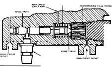
PROPORTIONING VAL.VE SPRING
PLUG
FAilURE WARNING LAMP SWITCH
Fig. 5-Cross sectional view of spool valve and proportioning valve
(2) Position the cylinder bore vertically, carefully lower the spool assembly, spring end first, into the bore ensuring that the spring remains assembled on the spool. Care should be taken to ensure the spool assembly is assembled and positioned in the bore exactly as shown in Fig. 6.
NOTE: Should the spring become separated from the spool, replace with the turned down con on the spool.
(3) Assemble "0" rings onto the outside of the differ ential piston stop spacer and lubricate with clean brake fluid.
(4) Locate spacer in bore and push against shoulder. (5) Assemble "0" ring onto end plug and screw into end of bore.
NOTE: The plug must be hand screwed until the head of the plug is 1,6 mm (1/16") under the mount ing flange, then tighten to specified torque.

ELECTRICAL SPRING ( •• curely •••• mbled with turned down coil on .pool)
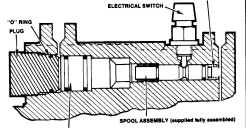
PISTON STOP SPACER
Fig. 6-Cross sectional view of spool valve and piston stop spacer
REV. OCT. '78
...