(5) Remove the pressed steel end cap fitted to the opening of the main bore by prising up the two locating lugs.
NOTE: Hold the cap firmly with one hand during this operation, to ensure that the primary piston does not spring out of the bore when the cap is removed.
(6) Remove the primary piston and return spring.
(7) Fully depress and hold the secondary piston down the bore and then remove the reservoir attaching bolt from the cylinder body.
(8) Remove the secondary piston and return spring by using compressed air or lightly tapping the open end of the cylinder bore squarely on a soft piece of wood.
(9) Unscrew and remove the brake failure warning light switch.
(10) Unscrew and remove the hexagon plug located at the flange end of the cylinder.
(11) Remove the seal block and piston assembly. If the assembly is stuck in the bore, tapping the flange end of the cylinder on a soft wooden block will assist removal.
(12) Remove the large spring and pressed steel poppet retainer, if necessary, long nose pliers will assist in re moval.
(13) Withdraw the poppet valve and spool valve assem bly using long nose pliers.
NOTE: The poppet valve must be gripped on the outer diameter, not on the cone section, other wise the surface will be damaged.
If the poppet valve separates from the spool valve assembly, remove the spool valve assembly, using long nose pliers to grip the poppet valve retaining extension on
| the spool valve. | . |
Inspection
(1) Clean all parts in clean methylated spirits and in spect for chipping, excessive wear or damage.
(2) Check all recesses, openings and internal passages, ensuring they are open and free from foreign matter. Use compressed air to blow dirt and cleaning solution from all parts.
(3) Inspect the master cylinder bores for signs of etch ing, pitting or scoring. If the bores are unsatisfactory in any of these respects, the master cylinder MUST be re placed.
NOTE: The cylinder MUST NOT be honed.
Assembly - Master Cylinder Main Bore
NOTE: When using a master cylinder repair kit, all the new parts must be installed. The proportion ing valve seal block and piston assembly is pre lubricated and MUST NOT be washed, it must be assembled as supplied.
REV. OCT. '78
5 - 3A - 4
(1) Before assembly, lubricate all parts (see note) and master cylinder bores with clean brake fluid.
(2) Install "0" ring seal into the smaller of the two grooves at the end of the secondary piston.
(3) Install one of the three identical cup seals into the second groove, ensuring that the seal lip faces away from the "0" ring seal (refer Fig. 2).
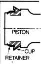
(4) Install one of the three identical cup seals into the shallow seal groove at the return spring end of the second ary piston, ensuring that the seal lip faces away from the "0" ring previously installed (refer Fig. 1). Locate part of the plastic cup seal retainer in the groove on the piston and hold in position with thumb (refer Fig. 3). Using a small pointed tool, clip the retainer into the remaining part of the groove ensuring complete location is achieved and that damage to the piston or cup seal is avoided.
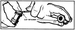
Fig. 3-Fitting plastic cup seal retainer
NOTE: Retainers should be discarded if pistons do not have locating grooves as shown in Fig. 4.
SECONDARY PISTON

,
) CUP RETAINER GROOVE
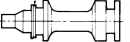
PRIMARY PISTON
Fig. 4-Pistons with cup retainer groove
.
(5) Install the third identical cup seal into the primary piston groove located on the return spring end of the piston. The seal must face away from the push rod end of the piston (refer Fig. 1). Fit the remaining plastic retainer to the primary piston as detailed previously.
(6) Install the secondary seal into the groove at the push rod end of the primary piston, ensuring the seal lip faces away from the push rod end of the piston (refer Fig. 1).
(7) Fit the secondary return spring into the end of the secondary piston and spring end first, carefully install the piston assembly into the bore.