GENERAL INFORMATION
The single piston, sliding caliper disc brake assembly consists of the hub and disc assembly, caliper, shoe and linings and a splash shield.
The cast iron braking disc has cooling fins that are cast integrally between the two machined braking surfaces. When the wheel is in motion, the rotation of the disc cooling fins supplies air circulation between the braking surfaces for efficient cooling of the disc and prolonged lining life. The braking disc is protected from road splash (inboard side) by a shield bolted to the steering knuckle and by the wheel and tyre on the outboard side.
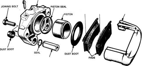
The caliper has been designed to conserve weight and provide ease of service. It is a single cylinder, two sleeve, tloating type. Braking torque is absorbed by two bolts in shear, which extend through the sleeves into the steering knuckle assembly. Because the bolts screw into the knuckle, the conventional torque plate or anchor bracket is eliminated, thus reducing weight. The pad support is nodullar iron and the cylinder is aluminium.
The steel piston is nickel and chrome plated for anti corrosion and long wear. The square cut rubber piston seal is located in a machined groove in the cylinder bore and provides a hydraulic seal between the piston and the cylinder wall.
A moulded rubber dust boot installed in a groove in the cylinder bore and piston keeps contamination from the cylinder wall and piston.
As the brake pedal is depressed, hydraulic pressure is applied against the piston. This force is transmitted to
CALIPER BODY
SLEEVE
5 - IB - 2
the inboard brake shoe and lining and the inboard braking surface of the disc. As force increases against the disc from the lining, the caliper assembly moves inboard, sliding on the mounting bolt sleeves, thus providing a clamping force on the disc.
When the brake pressure is released, the piston seal (distorted by applied pressure) returns to its normal posi tion, pulling the piston back to released position (Fig. 2), creating a slight running clearance between outer shoe and the disc.
Automatic adjustment is obtained by outward reloca tion of the piston as the inboard lining wears and the inward movement of the caliper as the outboard lining wears, thus maintaining correct adjustment at all times.
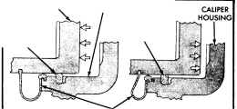
PISTON PISTON SEAL BRAKE PRESSURE
ON
CYLINDER BORE
PISTON SEAL BRAKE PRESSURE OFF
DUST BOOT
NN427B
Fig. 2-Piston seal function for automatic adjustment
ANTI-RATTLE CLIPS
/)
PAD SUPPORT
Fig. l-Caliper assembly-disassembled view ISSUE AUG. '77